
【STM32N6570-DK评测】开发环境及LED debug
找到下载工具包下的文件STM32Cube_FW_N6_V1.0.0\Projects\STM32N6570-DK\Examples\GPIO\GPIO_IOToggle\STM32CubeIDE导入到项目。注意:Boot模式,RAM启动使用:BOOT0(1-2)和BOOT1(1-3);外部flash启动使用:BOOT0(1-2)和BOOT1(1-2)把STM32N6570-DK开发板BOOT1拨到
|
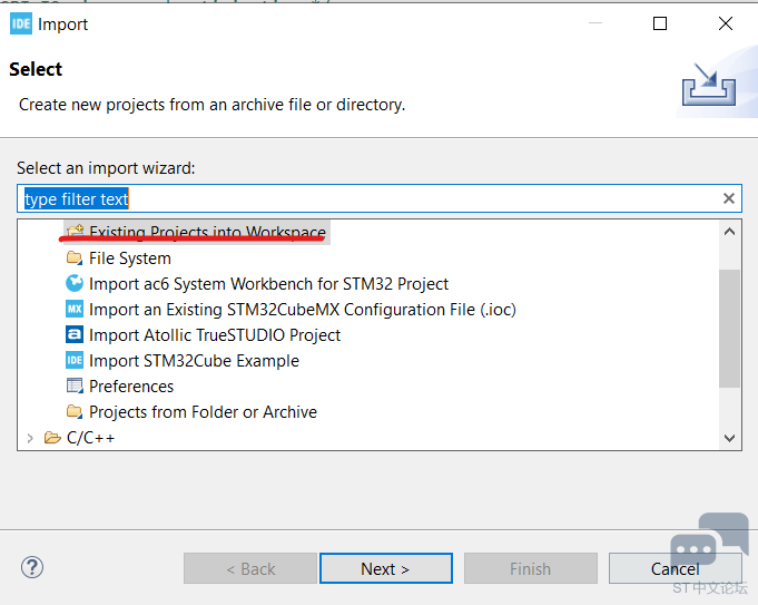
STM32N6570-DK评测】CubeIDE开发环境及LED 拿到STM32N6570-DK使用CubeIDE开发。搭建开发如下。 使用CbueIDE更新开发库STM32Cube_FW_N6_V1.0.0。 打开CbueIDE, 在Project Explorer框右键“Import...".
然后"Next"如下:
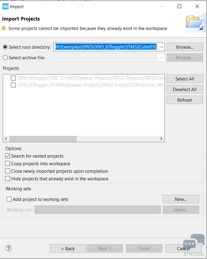
找到下载工具包下的文件STM32Cube_FW_N6_V1.0.0\Projects\STM32N6570-DK\Examples\GPIO\GPIO_IOToggle\STM32CubeIDE导入到项目。如下图:
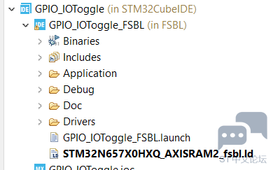
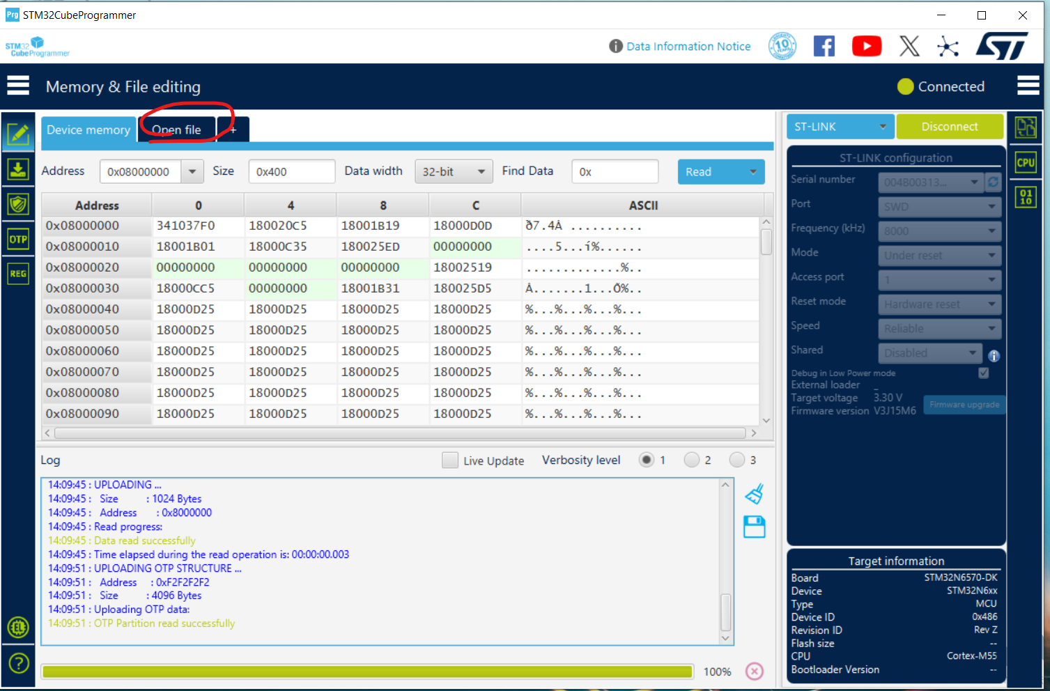
接着右键“clean Project",再”Build Project"。 把STM32N6570-DK开发板BOOT1拨到1-3。然后插入CN6 “STLINK V3EC”接口,连接到PC。 然后右键debug GPIO LED。debug run后,可以发现LED1闪烁。 如果需要下载到外部flash上启动。需要以下步骤。 Next, this program can be run in boot from flash mode. This is done by following the instructions below:
使用CubeProgrammer。
注意:Boot模式,RAM启动使用:BOOT0(1-2)和BOOT1(1-3);外部flash启动使用:BOOT0(1-2)和BOOT1(1-2) |

一站式 AI 云服务平台
更多推荐

 0
0 0
0- 0


 已为社区贡献1条内容

所有评论(0)